Process Flow Diagrams (PFDs) vs. Data FlowDiagrams (DFDs) in the Modern ThreatModeling
Apr 24, 2025
Process Flow Diagrams (PFDs) vs. Data Flow Diagrams (DFDs) in the Modern ThreatModelinga
ARENA
AUTHORS
| Alex Bauert | Archie Agarwal | Stuart Winter-Tear | Dennis Sebayan |
| alex.bauert@threatmodeler.com | archie@threatmodeler.com | stuart.wintertear@threatmodeler.com | dennis.sebayan@threatmodeler.com |
Abstract
Originally popularized by Microsoft in their Open Source Threat Modeling Tool (TMT), data flow diagrams (DFDs) have been the de facto approach to threat modeling in the Information Security profession. As the technology industry has moved towards rapid iterative modular development and deployment, the flaws in continuing to use DFDs have become painfully obvious. This short paper puts forward some of those flaws and the advantages of moving to a more mature Process Flow Diagram (PFD) approach to threat modeling as a solution.
What is Threat Modeling?
In Information Technology, Threat Modeling is the intellectual process of enumerating potential threats to a system (“Evil Brainstorming”) and providing mitigations to those threats. This encompasses identifying, communicating and understanding the potential threats posed to the system.
Ideally this process would be undertaken as early in the development and planning stage as possible. It is far cheaper to engineer security into something while designing and building it, rather than reconfiguring or rebuilding afterwards.
Threat modeling should not be a one time activity but an ongoing process throughout the development life cycle and continue into production in an iterative manner as changes take place in the system.
Purpose of This Paper
For a number of reasons, including adoption by Microsoft in their Threat Modeling Tool, traditionally threat modeling has leveraged the Data Flow Diagramming process (DFD). It is this paper’s contention that DFDs are outmoded and inadequate in a modern, fast-paced, fast-changing, operational and development environment.
Process flow diagrams (PFD) in contrast are perfectly suited to uncover and mitigate potential threats to modern systems.
After a more expansive definition of PFDs, DFDs, VAST and STRIDE, the shortfall of DFDs and the benefits of PFDs will be explored in relation to the STRIDE mnemonic and VAST methodology.
Definitions
Data Flow Diagrams (DFDs)
DFDs provide a high-level visualization of how data moves through and within a system, i.e., as it flows from node-to-node. A typical DFD contains a series of endpoints with distinct, unidirectional and bidirectional data flows. Components are organized based on action/ behavior.
Process Flow Diagrams (PFDs)
Process flow diagramming (PFD), is a visualization process specifically created for threat modeling. Rather than looking at how the data flows through a system, PFD shows how a user or an attacker moves through the various features of an application. [1]
STRIDE
STRIDE provides a mnemonic device for security threats categorized as Spoofing Tampering, Repudiation, Information disclosure, Denial of service, Elevation of privilege.
The STRIDE threat modeling goal is to get an application to meet the security properties of
Confidentiality, Integrity, and Availability (CIA), along with Authorization, Authentication, and Non-Repudiation. Once the security subject matter experts construct the data flow diagrambased threat model, system engineers or other subject matter experts check the application against the STRIDE threat model classification scheme. STRIDE most commonly leverages DFDs based on data flow and trust boundaries. [2] STRIDE leverages DFDs.
VAST
The Visual, Agile, and Simple Threat modeling (VAST) methodology was conceived after reviewing the shortcomings and implementation challenges inherent in the other threat modeling methodologies. The founding principle is that, in order to be effective, threat modeling must:
-
- Scale across the infrastructure and entire DevOps portfolio
- Integrate seamlessly into an Agile environment
- Provide actionable, accurate, and consistent outputs for developers, security teams, and senior executives alike.
A fundamental difference of the VAST threat modeling methodology is its practical approach. VAST recognizes the security concerns of development teams are distinct from those of an infrastructure team.[2]
As part of this, the entire attack surface is analyzed (meaning all threats cumulatively) and the focus is on reducing that attack surface, as opposed to zoning in on components in isolation and mitigating individual threats as in STRIDE.
VAST leverages PFDs.
Shortcomings of the Data Flow Diagramming (DFD) Approach in the Modern Era
DFDs are detailed flowcharts first developed in the early 1970s when applications were created to run on a specific infrastructure. At that time, considering threats to an application separately from the 43% infrastructure would not make sense.
Compare that to today’s interconnected cyber ecosystem, in which applications are developed to be platform independent, and particular threats exist because of the interactions between applications and shared infrastructure components. Today’s production and operational environments are entirely different from the situation which gave rise to DFDs as a useful analytic tool.[3]
DFDs tend to a very high-level view of the system and are traditionally oriented to the STRIDE mnemonic categories that Microsoft developed. As a consequence, the generated threats tend to be genericized, focused primarily on the component type level, data flow and trust boundaries, with high-level attributes.
Generic components do not sufficiently match the reality of an architecture. Additionally, they drive generic statements about what can go wrong within an architecture. In a larger, more complicated architecture, threats may repeat without additional understanding of what is the difference between them. This is fundamentally a problem of lack of context endemic in the DFD approach.

False Positives, False Negatives and a False Sense of Security in DFDs
In today’s interconnected environment, building a high level diagram leads to false positives, false negatives and a false sense of security.
The genericizing of components and threats such as in DFDs yields a higher quantity of false positives. This approach makes it difficult to scale in large enterprises. A lot of training on the part of developers is required to understand DFDs. To quote Tom Holodnik, a software architect at Intuit,
“DFDs are a completely new language for developers and require a huge learning curve and constant oversight, whereas process flow diagrams (PFDs) are the language they speak and comes to them naturally.”
False positives occur when the threat model identifies security threats that aren’t valid. These threat assertions are stated as applicable, but are in fact driven by the data flow and do not recognize the context associated with the component. This lack of contextualizing tends to result in false positives. A prime example may be a component upstream or downstream that mitigates the threat identified in the component being analyzed, but this mitigation is missed due to lack of context.
Architectures may have repeating components (architectural patterns) and threats (threat patterns), but the severity and impact may be different. It could be the case for example that an identified threat does not in fact apply in the context of using a browser. But if you have a number of user objects within an area with the same types of attributes – specifications that define properties of an object, element, or file – how do you distinguish between them?
DFDs rely upon the sensitivity of the data at flow coupled with trust boundaries and it is the contention of this paper that this does not provide sufficient context within which to validate an identified threat. And this may give rise to false positives.
False negatives are the exact opposite, wherein the threat model misses threats that actually exist within your applications. This is particularly prone to happen in DFDs by focusing on components in isolation only, and missing other critical concerns such as the underpinning architecture. (This is covered in more depth later in the paper.)
Unfortunately both false negatives and false positives incubate a false sense of security.
DFD Threat Modeling Is an Incomplete Process
A focus on data flow over component type tends to provide less context than is needed to surface actionable requirements, which should be based on clear and specific threats. Threat modelers need refined component details providing the necessary clarity to shape the interactions and, by extension, threats and security requirements.
“DFDs are a completely new language for developers and require a huge learning curve and constant oversight, whereas process flow diagrams (PFDs) are the language they speak and comes to them naturally.”
Tom Holodnik .Intuit Software Architect
DFD Boundary Objects Don’t Depict
Accurate Threat State
Irrespective of the context of the web application component, within DFDs, if there is more than one, they will be accorded the same threats and mitigations. There is little or no consideration for potential mitigations provided by upstream or downstream components.


IMAGE FROM MICROSOFT’S THREAT MODELING TOOL
Rule Making With Boolean Logic Is Costly, Introduces Room for Error
Out-of-the-box automated threat modeling software based on DFDs such as Microsoft’s Threat Modeling Tool (TMT) treats all threats paired with a component as part of the threat landscape irrespective of the validity of their inclusion.
In order to overcome this lack of context, rules must be derived driven by Boolean logic (for example, “data flow contains local DMZ boundary”). When logic and context are added by these rules, there is the possibility to introduce complexity and error.
Threats derive value from the rules created for them based on the creation of specific rules for certain threats in which a respective trust boundary would change the number of threats.
Technology development teams can define rules that help decide whether or not a threat should show up but the rulemaking does not take into consideration threats related to the trust boundary itself. Threats are paired with components, not trust boundaries.
In summary, TMT trust boundaries have shortcomings as they:
- Are only used to provide a permutation for a rule.
- Use trust boundaries to show how the data flows across the boundaries, e.g., from one network to the other (a characteristic of DFD).
- Don’t have any threats associated with trust boundaries – you need to add your own.
DFDs Miss Contextual Information of End Point Components
DFDs generate threats when a data flow connection is made between two components. While data flows aid in understanding a system’s properties and threats, validation of those threats should not be based solely on the communication between end points, as they are not the only place subject to attack; the infrastructure upon which software runs could also be subject. Threat modelers need the holistic view of the architectural value of each endpoint component.
Realistically, we don’t live by just what sits in the communication between end points. We must look at an architecture holistically, including the properties that the different end points bring and evaluate their architectural value.
This lack of contextualization has been recently discussed in an interesting short paper arguing for a dedicated, integrated threat modeling language:
“we argue that the use of DFDs forms a non-trivial roadblock towards more mature threat modeling approaches.” [6]
DFDs Miss Threats at Differing Layers of the System
Entry points for threats and vulnerabilities do not exist in isolation on an endpoint. They exist within the various layers of IT architecture and may appear for example:
- In the browser
- At the Web Application layer
- Directly in the application
- In the server where the application is installed
- Associated with the database
If a miscreant’s objective sits in the database, the attack vector may be through the ordering form. Equally, threat chaining may be employed in which by virtue of completing one threat, the malicious actor can exploit another threat leading to the database.
By focusing almost exclusively on the component endpoint, threats at differing layers may be missed in the DFD
DFDs Are Time Consuming
DFDs are notoriously difficult to understand and, as the DevSecOps community has not embraced them due to their focus on:
- Very high-level design issues
- Complexity
- Vague nature
These experts are in scant supply, meaning a DFD will have to wait until one becomes available.This often leads to a delay and unwillingness to participate, which can only be overcome when threat modeling is a self-service exercise whereby all stakeholders can participate.

Advantages of the Process Flow Diagramming (PFD) Approach in the Modern Era
In stark contrast to Data Flow Diagrams (DFDs), Process Flow Diagrams (PFDs) focus on the progression of the user flow rather than data flow. The focus is on how the user interacts with the system from beginning to end including any deviation en route.
This vantage maps well to the world of product design and development, which in a modern Agile environment, tends towards focusing on features and functionality.
The PFD approach provides a visual decomposition of how the process specification is ordered and this is especially true when leveraged in conjunction with the Visual, Agile, Simple, Threat Modeling methodology (VAST).
This culminates in a real world view of the system being analyzed rather than interposing the rigid Data Flow approach.
And all of this leads to other benefits that are detailed below:
PFDs Provide a Holistic View
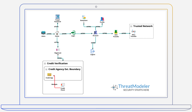
PROCESS FLOW DIAGRAM OF AN ONLINE BANKING APPLICATION FROM THE THREATMODELER™ PLATFORM
As can be seen in the above Process Flow Diagram, the architecture is broken down into various features and use cases: Login, Funds Transfer, Password Reset, Third Party Credit Verification and so on.
The communication protocols are also identified, which facilitate users traversing between functions and features. The various technical controls in place are also identified including: Forms, Cookies, Sessions, etc, that make up the feature movement.
This use case view provides threat modelers with a holistic aspect enabling them to pinpoint upstream and downstream technical controls already in place – thus avoiding the Data Flow Diagram problem o false positives.
PFDs Mesh Well With the Modern DevSecOps Process
Focusing on use cases is conceptually similar to how developers create applications, particularly in an Agile environment, making PFD outputs very accessible to the entire development team.
As a result, this puts the entire threat modeling process within reach of the developer teams, which ultimately – over time – should lead to a self-service approach to threat modeling; thus reducing the pressure on the security team while at the same time instilling security knowledge and knowhow in those developer teams, which is at the very heart of the DevSecOps movement.
The output is actionable, accessible and prescriptive to the Developer teams as they are premised on ordinary abuse cases (process abuse). This is in stark contrast to the standard DFD output, which tends towards:
- High level
- Descriptive
- General
Developer teams are left having to work out for themselves how the mitigations should be managed and put in place.
PFDs Facilitate Collaboration and Speed
As Process Flow Diagramming is viewed through the same lens as DevSecOps view their systems (easy to understand), this facilitates collaboration across all stakeholders, irrespective of subject matter expertise. A consequence is a self-service approach, which in turn releases the bottleneck security teams have traditionally experienced. This push for collaboration can be weaved into the design phase, saving further time by developing systems securely from the beginning rather than bolting security onto the end of the process.
PFDs View the System through The Eyes of the Attacker
Much like Developers, Hackers do not think in terms of data flows.
In the first phases of an attack (reconnaissance), miscreants traverse the application in a manner rather like a standard user, while simultaneously scoping and observing potential critical points of entry. The attacker is looking to subvert standard usage at these critical junctures in order to reveal vulnerabilities.
As the focus of the attacker is on abusing ordinary use cases (process flow abuse) and the threat modelers job is to reach into the mindset of the attacker, it makes sense for practitioners to view the architecture as a process flow to reveal the natural progression of an attacker and shore up any potential vulnerabilities. [3]
PFDs Aid in Identifying Potential Attack Vectors
In the case of Data Flow Diagramming, the asset to protect is viewed through the scope of data. Data has two states in the DFD world – stored and traveling. This view gives rise to analyzing the endpoint components (stored). This vantage may skew the reality when predicting potential attack vectors. A cybercriminal interested in attacking a database and traversing through the system as a user will realize the most potentially vulnerable entry point to the database may in fact be the login page, or search fields and forms, through which s/he could submit code rather than data. The hope being flawed sanitization with the database responding as though it were receiving commands through code. Thus revealing private data.
DFDs tend towards focussing on the database component itself and from that view it is all too easy to miss the true potential attack vector, which would be identified when viewed as a process flow.
PFDs Aid in Identifying Potential Attack Vectors
As PFDs are perfectly and specifically designed to illuminate an attacker’s process and path through to potential exploitation, threat modelers become aware of the true attack vectors. The information gleaned may be leveraged for pentesting and red-teaming. It makes sense for PFD-based threat modeling to drive testing rather than the traditional approach of “throwing the system over the wall,” hoping testers come to realize the correct weak spots.
Pentesting and red-teaming are constrained by time and the black-box approach compounds this. With PFD-driven threat modeling output in hand, testing teams are freed from approaching blindly and can more usefully utilize their time getting to the heart of testing potential vulnerable points.
PFDs Help to See the Infrastructure
Threat modeling should not only consider components in isolation, which is a major criticism of the Data Flow Diagramming (DFD) approach. The Process Flow Approach (PFD) also breaks the architecture down into various features and use cases. The communication protocols are also identified, which facilitate users traversing between functions and features.
This all provides context and, coupled with the Visual, Agile, Simple, Threat modeling (VAST) methodology, widgets are used to identify the infrastructure underpinning each component.
This Is Termed Operational Threat Modeling:
“Development teams and infrastructure teams need specialized threat modeling practices in order to optimize each of their unique security requirements. The VAST threat modeling methodology lists these two practices as application threat modeling and operational threat modeling, each delivering key
business benefits to maximize business security efforts.
[Operational threat modeling] allows organizations to visualize the “big picture” of its infrastructure risk profile and enhance the understanding of the full attack surface for key stakeholders. By utilizing operational threat modeling, organizational leaders are equipped to plan and prioritize infrastructure risk mitigation strategy.
The first step in operational threat modeling is to identify the operational environment, including shared components (i.e., SSO servers, encryption servers, database servers, and so forth). Next, consider every component’s attributes to provide additional context to the potential threats. For example, a database
which has unrestricted admin access or large quantities of confidential data may have more potential threats than others. Finally, the potential threats and known common vulnerabilities [and exposures] (CVEs), both internal and external, may be systematically identified and the relevant security controls
enumerated.” [4]
PFDs for Standardization
Since a DFD does not analyze an application from the perspective of an attacker utilizing process flow, any predictive capacity regarding possible attack vectors, entry points, or exfiltration points requires significant speculation on the part of the modeler.
The PFD process lends itself to standardization – the same outputs and benefits can be realized regardless of who creates the model.
By leveraging PFDs, the relevant potential threats and appropriate mitigating controls are identified by constructing the threat model from the perspective of user interaction (process flow). This gives rise to systematically processed and standardized modelling.
PFDs Suited to Agile Development
Threat modeling using the traditional Data Flow Diagramming (DFD) approach has had a hard time being accepted in a modern, fast-paced Agile development world.
The many reasons for this are clear as elucidated in this paper, but most notably due to the approach being:
• Very time consuming
• Alien to developers in terms of system view
• Demanding of security subject matter experts
Ultimately, the raison d’être for threat modeling is to help developers create inclusively secure code from the beginning of the development life cycle, enhancing their Agile sprints to the production finish line and significantly reducing remediation costs for vulnerabilities found during the scanning phase.
By virtue of their high level view, DFDs tend to be vague, unwieldy and unproductive in an Agile environment, reducing them to little more than a theoretical exercise that development teams tend to minimize. By comparison, process flow diagrams (PFDs) create a visual representation of applications that are very similar to the way developers think through the coding process – in terms of features, communication between those features, and the various building blocks that make up the features. The result is a threat model that developers can embrace because it speaks their language and adds efficiencies to their sprints.
From an Operational perspective, if cloned, additional databases are required, e.g., for scaling. This does not necessarily equate to additional threats, as mitigations should already be in place either upstream or downstream. By virtue of focusing on components in isolation, DFDs would create additional unnecessary threats for each database, unlike the PFD approach, which has the advantage of being both holistic and contextual.
Conclusion and Outlook
Change can be difficult, but is vital for progress.
The Information Security profession is undergoing seismic changes as it grapples with the concept of engineering security into the early phases of an ever increasingly fast SDLC (proactive) rather than finding flaws to fix at the end (reactive).
Threat modeling is becoming understood as the perfect bridge to achieve this, but many have grown disillusioned with the industry standard Data Flow Diagram (DFD) approach.
The point of this paper was to highlight the significant problems in DFDs and the advantages of PFDs. It is a difficult thing indeed to unseat the predominant methodology, hence why the authors of this paper took this stark approach.
It could well be, a way can be found for these two approaches to compliment one another and some researchers are exploring exactly this [7], but one thing is for sure in the minds of the authors of this paper: DFDs must not continue to be the only path for threat modeling and PFDs present an opportunity to move forward and mature this worthy endeavour.
About ThreatModeler Software Inc.
ThreatModeler is a commercial platform that empowers DevSecOps to protect their IT environment and applications through automated threat modeling. With a fraction of the time and cost tied to other threat modeling tools, users can design, build and manage security from development to deployment. Teams can instantly visualize their attack surface, understand security requirements and prioritize steps to mitigate risk. ThreatModeler executes security validation by facilitating a highly collaborative user experience that clearly articulates security posture. CISOs can make critical securitydriven business decisions to scale their infrastructure for growth.
ThreatModeler is contributing its industry leading technology to embolden the DevSecOps community to continuously prioritize the protection of their applications – at no cost. ThreatModeler’s Community Edition can be accessed via https://community.threatmodeler.net. It enables developers to upload TMT Data Flow Diagrams (DFDs) files for automatic conversion into Process Flow Diagrams (PFDs) to uncover all IT environment threats in minutes. DevSecOps can use the insights gained from the threat report to confidently build security into their code.